إعـــــــلان
تقليص
لا يوجد إعلان حتى الآن.
جهاز استشعاري سهل الصنع
تقليص
هذا الموضوع مغلق.
X
X
-
الكلمات الدلالية (Tags): detector, detector metal, detectors, detectors gold, exp 4500, fisher f75, fisher75, gold detector, gold detector scanner, gold detectors, gold jeohunter, goldكشف الكنز, gpx 4500, gpx4500, how to make metal detector, jeohunter, jeohunter 3d, jeohunter 3d detector gold, jordan detector, metal detector android, metal detector sensor, mf 1100, okm metal detector, okm metal detectors, real gold detectors, real okm metal detectors, top detector, underground metal detector, أجهزة البحث عن الذهب, أجهزة الكشف عن الذهب, أجهزة الكشف عن المعادن, أجهزة كشف الذهب, أجهزة كشف الذهب والكنوز, أجهزة كشف الكنوز, أجهزة كشف المعادن, أسواق الذهب بالرياض, أسياخ النحاس للبحث عن الذهب, أسياخ النحاس للبحث عن الذهب والمعادن, اثار الذهب, اثار تحت الارض, اجهزة اكتشاف الذهب, اجهزة البحث عن الاثار, استشعاري, الصنع
-
Ranger-Tell Examiner
by Carl Moreland
Of all the LRL reports I've written, this has been the most difficult. Not because of the complexity of the device — the Examiner is actually very simplistic and easy to analyze — but because of the sheer amount of information available to wade through. The Ranger-Tell has far more content than any other LRL manufacturer web site and, besides being horribly arranged and presented in a visually painful way, the writing style is often incomprehensible. Add to that the significant presence of the manufacturer on Internet forums, and long-running eBay sales, and we have way more nonsense to deal with than the average LRL.
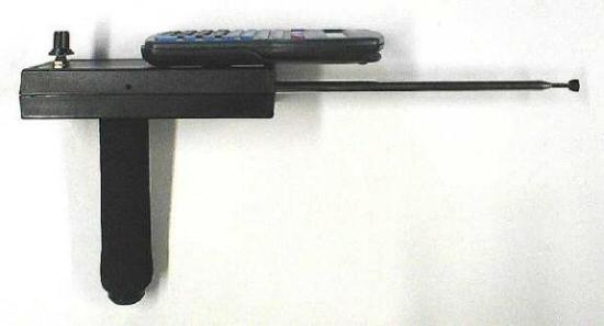
Fig. 1: Ranger-Tell Examiner. The Ranger-Tell Examiner is a so-called long-range locator that supposedly can locate gold (specifically) and other targets of interest in general. The Examiner is one of a few models1 produced by "Ranger-Tell" in Australia, and often sold directly on eBay. The current Examiner (called the "TG" or "Targette-Garvin" model) sells for $750-$800, depending on the exchange rate. This particular unit was purchased directly from Ranger-Tell, and not via eBay.
First Look
Fig. 1 shows a side view of the Examiner. It consists of a black box with a swivel handle on the bottom and a collapsible antenna sticking out the front, very much like the designs of the What differentiates this LRL from the others is the calculator that is attached to the top of the black box.
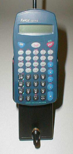
Fig. 2: Top view showing the calculator. Fig. 2 is a top view that shows the calculator, which is a Karce KC-153. Karce is based in China, and makes dirt cheap calculators and electronic organizers. I could not find this particular model for sale (probably discontinued), but similar scientific models sell for $5 or so. The calculator is mounted in a slip case, which is attached to the black box. It easily slides out of the slip case, revealing the view shown here:
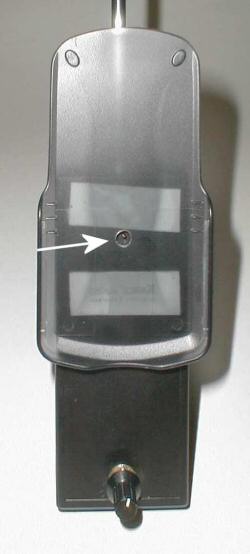
Fig. 3: Behind the calculator. The first thing to note, is that the calculator slip case is attached to the black box with double-stick foam tape. A second item of interest is that the slip case has a hole drilled in it, and there is a wire sticking up out of the black box through this hole. The wire is not connected to the calculator, and is trimmed flush so that it does not even touch the calculator when it is slid into the slip case.
Besides the calculator, there is one unmarked control knob at the top rear of the black box. Additionally, there are three small holes in the box — two on the bottom and one on the right side — that appear to be access holes for inserting a screwdriver to adjust whatever is inside the black box.
The antenna is a common telescopic radio type and extends to XX inches (XX cm). Finally, the black box has a battery compartment, but the cover is permanently glued shut, and there is no provision for installing a battery, other than the ones contained in the calculator.
Closer Look
With most LRLs, opening the "black box" usually reveals what the whole thing is all about, and the Examiner follows this trend perfectly. The case for the Examiner was well-glued, and difficult to open, but revealed the following interior2:

Fig. 4: Inside the Examiner. The upper half (on the left) holds the lone external control, a potentiometer. I've disconnected the two wires that connect it to the remaining circuitry in the other half, in order to fully open the case. Additionally, glued to the inside top is a piece of heavy-gauge enameled copper wire that is bent around and back-and-forth, in a rather meandering way. One end of this wire protrudes through the top half (see arrow), and through the hole in the calculator slip case (arrow, Fig. 3). Neither end of the wire connects to anything, anywhere. It's just a piece of disconnected wire, glued to the box.
The bottom half of the black box holds the antenna, a small circuit board, and more wire. A piece of brass rod is also affixed to the inside of the lower half, and protrudes through the case to form the core of the handle. The rest of the handle consists of a plastic tube and end caps (similar to PVC pipe sold in the US), along with a soft foam grip, and the brass rod is inserted through holes in the end caps such that the plastic tube (and foam grip) will spin on the brass rod, creating a pivoting handle. Fig. 5 is a disassembled view of the handle, and the circuit board inside the Examiner has been moved upward to reveal the mounting details. The red arrow shows where the brass rod comes through the case and is bent over and secured to the case with a screw.
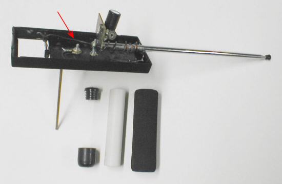
Fig. 5: Details of the handle. The rear of the antenna is mounted to a screw, secured through the bottom of the case. One of the leads from the external control potentiometer (mounted in the upper half of the case) is soldered directly to the rear of the antenna. The other potentiometer lead is soldered to the brass rod that forms the core of the handle. Therefore, the potentiometer is connected between the handle core and the antenna. The antenna is not electrically connected to anything else, nor is the handle core.
The small circuit board is an experimenter's type, often called "perf board". Normally found in one-off homebrew projects, and not in commercially manufactured equipment. Mounted on the board are 2 potentiometers, one variable capacitor, and one electrolytic capacitor. One of the potentiometers, and the variable capacitor, are mounted on the bottom side of the perf board (see Fig. 6). There are two small access holes (mentioned earlier) in the bottom of the Black Box to access them. The access hole in the side of the Black Box is for the other potentiometer on the top side of the circuit board. Fig. 6 also clearly shows where one of the potentiometer wires is soldered directly to the handle core.
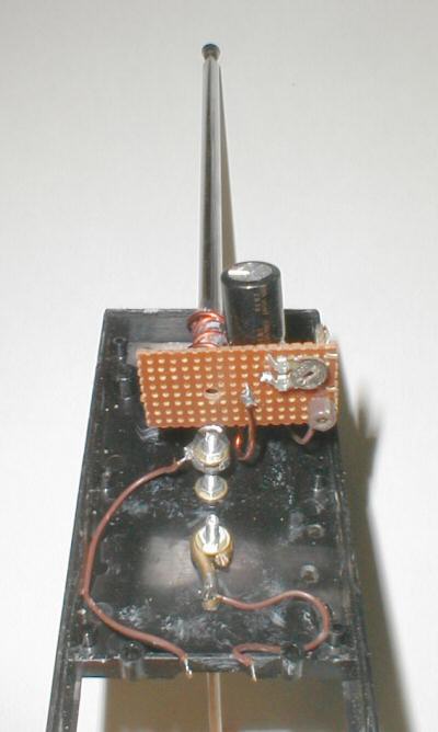
Fig. 6: Bottom side of the circuit board.
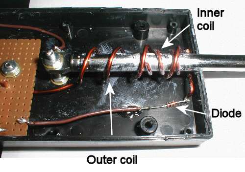
Fig. 7: Antenna detail. Fig. 7 shows a close-up of the antenna, which has two coils of heavy-gauge magnet wire wrapped around it. The smaller coil has three turns and, like the piece of meandering wire glued to the inside top half of the case, it is not physically connected to anything at all. The larger coil has 4 turns, wound in the opposite direction from the smaller coil, and is connected to other circuit components. The front end of the coil is connected to a diode (small-signal 1N914 type), which is then connected to the circuit board. The other end of the coil also connects to the circuit board.

Fig. 8: Examiner schematic. The schematic, Fig. 8, shows that the circuitry consists of a series connection of a diode and an RLC circuit, where the inductor is the enameled wire wrapped around the antenna. The second inner coil wrapped around the antenna (gray in the pic) doesn't connect to anything at either end, and therefore cannot possibly play any operational role in the circuit. The remainder of the circuitry is variable capacitor C1, electrolytic capacitor C2, and two potentiometers. The three variable elements in this circuit can be adjusted via small access holes in the Black Box, as already mentioned.
The Claims
There are four sources of claims for this device: the eBay listings; the user manual; and statements made by "Ranger" (the owner of Ranger-Tell) on various forums, in response to questions asked of his devices. Some of the many operational claims made of the Examiner are:- A long range locator that will find gold, precious metals and gemstones. (eBay)
- All RT units will detect coins and jewellery [sic] as well as reefs, caches, and any deposits of gold and precious metals and/or gemstones. They will also detect paper money. (web site)
- It will pick up 4gm gold in a vial from 25 meters dead on. (manual)
- Small items like coins and rings can be detected at tens of feet. (web site)
- The Examiner will locate a gold ring at 25 meters below the surface. (manual)
- It will detect larger metals and materials that are up to 1 kilometre away and generally much further. (manual)
- It will swing perceptibly towards large targets many meters below the surface and several hundred meters distance. (eBay)
- Plus it has found gold EVERY time it's been used this year on Australian Goldfields and continues to be amazingly popular worldwide. (eBay)
- Most people will only need it for nuggets and gold in general, which will be detected without fault at hundreds of meters distance and conservatively a hundred metres of solid rock. (eBay)
- But then since the Earth is a magnet and it is the polarity plus the resonant frequency amplification circuit of the unit that causes it to turn, it is in fact a gold and substance compass and hence distance is no object. (web site)
- The Ranger-Tell Examiner uses a powerful frequency induction system turned to maximise detection, and flawless electronic circuitry. Since it is based on original aerial physics there is no battery power required. (eBay)
- The range of this detector is Unbelievable!! (eBay)
Each entity in the universe is made up of an atomic structure that makes it that particular entity. In simple terms if you can imagine the atoms vibrating in these objects you will see that there will be a high and a low to each vibration and that eventually the same vibration pattern will occur. This is the frequency of the oscillating or vibrating object. Each object has it's own frequency. When you tune to a sample of that object the electronics in the locator will resonate or harmonise with the same vibration in the target and the alignment of the barrel will occur as it attempts to find the correct magnetic polarity between the unit and the target.
The manual for the Examiner also includes a similar theory:
HOW DOES IT WORK? There is considerable debate regarding the real explanation for the locating power of LRLs generally. The answer is in the physics of magnetic currents, resonant frequency and coil principles e.g. induction. The target, like all things has it's own specific frequency. The coil antenna within the unit can amplify that frequency once it detects it. It detects it because you have set the Examiner to the target's frequency by entering the number. When the antenna encounters a similar frequency in the field it begins to vibrate or resonate at the same frequency in Hertz which is another word for cycles per second. It does this because of the unique coil system within that is sensitive to similar vibrations, like a radio is sensitive to radio waves and not microwaves. On being amplified by the circuitry in the Examiner the magnetic govern it's disposition for it to align with the target's direction.
This is pretty much the same "theory" that is promoted by other LRL manufacturers: that each something3 has its own unique frequency, and if the LRL is tuned to that frequency, it will point to the desired object.
According to the manual and the web site, the calculator is used to program the desired operation frequency:
[The calculator] produces an amplifiable signal that is filtered and induced by the control box circuit to turn the unit into a specifiable compass, according to the specific frequency entered in it.
Furthermore, it is claimed that the resulting frequency is accurate to no less than 9 decimal places:
The Examiner will give you nine decimal place accuracy due to research with special signal generation systems into just exactly what frequencies are involved with gold, precious metals, and gemstones.
The instructions say to enter a number — say, 5.11 for gold — and to hit the "SIN" key (mathematical sine) to "program" the unit. The manual goes on to say that additionally pressing the "HYP" key (hyperbolic) will "sharpen the response". The telescoping antenna can be adjusted for distance: "You can alter the range of the Examiner by extending [the antenna]".
Because the calculator is not electrically connected to anything, it is claimed that the resulting calculator-generated signal is coupled into the black box using the principle of induction, via the piece of meandering wire glued to the inside top of the box:
[The calculator] is in fact a DC oscillator that produces a steady, mathematically modified sin [sic] wave frequency signal to be translated by the Tesla coil and circuit in the control-box.
The piece of meandering wire is described as being part of a "Tesla transformer":
It is in fact an oscillator whose wave output is collected by the unique flat Tesla aerial as an induction field which needs no contact between components.
It is based on Tesla's work with flat spiral antennae.
The black box contains a simple series connection of components, unpowered, that is described as being both a resonant circuit, and a filter:
the specially selected rectification signal diode, the capacitance and resistance unseen and the main capacitance form a Tesla/Resonance circuit to enable the detection of frequencies inputted into the calculator.
The resonance circuit forms [a bypass filter] as well as far as I am aware.
The series connection of components includes magnet wire wrapped around the antenna, plus there is a second disconnected piece of wire also wrapped around the antenna. These are described as being the secondary coils to the piece of meandering wire, as follows:
Classic but unique Tesla coiling with deliberate reverse double helix winding that's not found anywhere. The winds and turning forms the secondary. It is basically A TRANSFORMER. This particular type of transformer is known as the Tesla coil after its inventor, Nikola Tesla. Unlike low-frequency transformers, it has an air core, and no iron is used in it construction.A short explanation of how the Tesla Coil converts the low-frequency ac into high-frequency ac is first necessary. there is no need for any connection to be made between wires and coils. This is the Tesla principle. It's in electric motors, transformers and pcs. It a field transference.
Once the desired numbers are programmed into the calculator, the lone control knob can be used as a "fine tuner", and "allows you to tune to sharper locks with your target", according to the manual. Yet, in another place the manual states the control knob "is like ground-balancing a standard metal detector", although there is no further explanation of this claim.
So, in summary, the claimed operation is as follows: The calculator is programmed by the user, and generates a particular frequency signal; the signal is inductively coupled to the meandering wire, which is described as the primary (flat spiral) coil of a Tesla transformer; the wire wrapped around the antenna is the secondary coil and, along with the series connected components, amplifies and filters the signal; the signal resonates with a distant target and causes the device to turn and point at the target.
__________________
تعليق


تعليق